
APC Back-UPS RS 500 수리 튜닝


이 제품에 대해 알아야 할 사항
위 설명에서 문제가 되는 콘덴서를 교체 해야 하는 상황이 발생시
구입해야 하는 콘덴서 부품
16V 22μF 85C
16V 22μF 105C
16V 47μF 105C
25V 22uF 85 ° C
C7은 제조사가 알려지지 않은 50V 22uF 105c를 사용
제품 윗 부분이 금색임
보통 22μ 정도면 충분하다고 하나 뒤에 붙는 온도부분이 높은것을
추천 하는듯하다. 85C → 105C 추천
아래글을 참고하세요 전 영어 무식자라..
Well, designers of this circuits were… (censored) I have had the same problem, analyzed the switching power supply and found the same problem. Consulting the data sheet of UC3842B, the 22µF capacitor seems to be underestimated. At least in RS500 230V version REV05 one of resistor around eats permanently about 2 Watts and generates a lot of heat. That is why I decided to do a more radical change: Replace the capacitor with much larger one: 220µF. Remove the parallel 3.3kΩ resistor R139 without any replacement. Replace large hot 50kΩ resistor R28 by 220kΩ of the same size (probably even more is possible). It decreases power current by 2 Watts and temperature there by 40°C at cost of 1 second delay after connecting the power plug. Purpose of such modification: Original design used a very hard divisor that divides the plug voltage to supply ~10mA. It is nearly enough for running the oscillator, so 22µF was (nearly) enough. But the divisor should be used just to start oscillation. Once the oscillator runs, it is powered from the transformer and the divisor is not needed. You can verify this fact by disconnecting the large divisor resistor, touch, and remove. Oscillator runs. The datasheet says, that when there is no power to run oscillator, the IC eats less than 0.5mA. It means, that the divisor could be designed to provide only 0.5mA, not 10mA. In this case, capacitor must be larger (e. g. 220µF), because the complete start of the oscillator is powered nearly exclusively from it. It must have enough juice to keep voltage above the minimal voltage until the transformer start to give power. Happy hacking Stanislav,
고열로 인하여 분제가 발생하는 저항 부속의 스팩 참고
R28 = 50K2W5 %,
R29 = 3,3K2W,
R75 = 2,2R2W,
R157 = 20R1 / 4W.
이 제품의 회로도
 APC UPS 500.rar


참고 웹페이지 : http://www.heime.org/post/17
Repair and improve broken APC UPS RS-500
Not charging
 One day my UPS stopped to charge the battery. After first look inside I found two resistors that were apparently broken (R150 and R151). Guessing from the relics of the parts, I replaced them by two 10Ω resistors. I think that these resistor pass in fire if your CRT is starting just in the moment of battery test or change of power type.
But it did not help, so I started to analyze the switching power supply and considered that the oscillator based on UC3842B is not working properly. First I suspected that the IC is broken, but later considered that it works, but the 22µF capacitor C7 seems to be underestimated and not sufficient to keep power for oscillator running in a standard conditions.
Symptoms
You can easily verify that your device is broken in the same way: Measure voltage on R139. If you get more than 11V, the oscillator is probably OK. Less than 10V means breakage mentioned here (my had about 8V). 0V means total breakage of the oscillator or blown resistor R139. Warning: There is a dangerous voltage on R139! Use an insulated voltmeter!
What is happening here?
- voltage reaches 12V, oscillator starts
- transformer oscillator slowly starts
- transformer oscillator still not reached fully working state
- voltage drops to 8V, oscillator stops
- voltage reaches 12V, and the loop repeats
Warning
Don't try to “fix” broken UPS by a plain battery replacement. Oscillator failure causes permanent discharge resulting in a battery fault. If you connect a new battery to a broken UPS without a fix, your battery will permanently fail in a few days or weeks and you will have to purchase new one again!
Some UPSes use high voltage electrolytic C22 capacitor. There can be a dangerous voltage several seconds after disconnecting it from mains. In case of blown resistor R139, dangerous voltage may remain there for hours or days!
Easy fix
Far the simplest fix of this problem: Replace C7 by a capacitor with a higher value, e. g. 47µF. It should start to work.
If the oscillator works properly, there should be about 13.65V on the secondary part. If it does not, the voltage is zero or very low.
Note that if charging was broken for more that few days, your battery is very probably dead and needs to be replaced as well. You may see Replace battery signal.
If you are not familiar with electronic repair work, you may consider to follow Repair instructions for APC Back-UPS RS 500 on Heime. It describes easy fix of the same problem in more detailed steps.
Complex fix
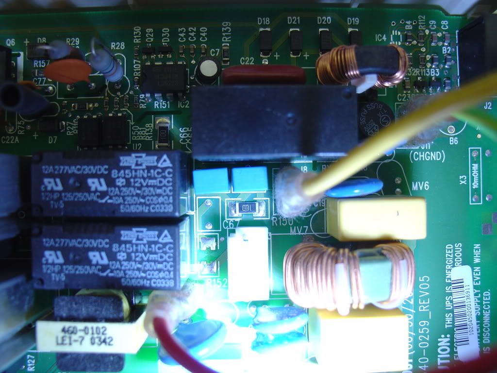
 Consulting the data sheet of UC3842B, I found yet another broken design: At least in RS500 230V version REV05 one of resistor around (R28) eats permanently about 2 Watts and generates a lot of heat. The temperature there is permanently about 90°C and it even causes degradation of the cover plastic (see the image).
That is why I decided to do a more radical change:
- Replace the 22µF capacitor C7 with much larger value: 220µF (16V should be enough). Use of a low ESR capacitor at 25V or 35V could be a better choice.
- Remove the parallel 3.3kΩ resistor R139 without any replacement.
- Replace large hot 50kΩ resistor R28 by 220kΩ of the same size (probably even higher values are possible at cost of a bit slower start).
This modification decreases power consumption of the bare UPS by 2 Watts and the temperature of the resistor by 40°C at cost of 1–2 seconds delay between connecting the power plug and oscillator start.
  |
Understanding the switching power supply
The FET Q6 is chopping the DC to T1 (winding 4-6) by grounding the pin 6 by some frequency. T1 then provides square AC voltage on winding 1-2, which is fed to U2 as DC again by D7/R50. Ferrites B8/B9 provides RFI shielding.
C7 also provides filtering for a smoother DC for U2 so a bigger capacitor would be better for that too. Winding 7-9 on T1 actually provides the charging current for the battery.
Technical description of the modification
Original design used a very hard divisor (R28 and R139) that divides the plug voltage and can supply about 10mA. It is nearly enough for running the oscillator, so 22µF was sometimes enough.
But the the resistor divisor should be used just to charge capacitor C7 and then use its energy to start oscillation. Once the oscillator runs, it is powered from the transformer (which gets its energy through 2SK2608 power FET) and the divisor is not needed for the regular work. You can verify this fact by disconnecting the large divisor resistor, touch, and remove. Oscillator runs until you disconnect the power.
The UC3842B data sheet says, that if there is not enough voltage to run oscillator, the IC eats less than 0.5mA.
It means, that the divisor could be designed to provide only 0.5mA, not 10mA. Additionally, low current of the divisor allow to omit resistor to the ground completely: The IC has a protection Zener diode (well, it should be never activated with the design used in this UPS – once the voltage reaches about 14V, regulation feedback (using opto-couplers) will prevent further raise of the voltage.
In this new design, capacitor must be larger than in the simple fix – e. g. 220µF. The complete start of the oscillator is powered nearly exclusively from it. It must have enough juice to keep voltage above the minimal voltage until the transformer starts to give regular power.
Computing the resistor R28 value:
- Any resistor of that size that survives 230V with a sufficient reserve (i. e. 600V peak voltage) can be used. Any resistor of the same size (or a bit larger) as the original should be OK.
- The value of the resistor: 150V (minimal power voltage with a reserve) / 0.5mA = 300kΩ
- Maximal power dissipation of the resistor (for 220kΩ): 280V (maximal power voltage with a reserve)² × 180kΩ (20% tolerance) = 0.436W
- I verified that combination R28 = 220kΩ, C7 = 220µF works well.
내용:
관련 : APC 돌아 가기-UPS RS 500에 대한 복구 지침 에 Heime , - 문제 해결 APC UPS 장치 에 Badcaps 포럼
고장난 APC UPS RS-500 수리 및 개선
청구하지 않음
어느 날 내 UPS가 배터리 충전을 중단했습니다. 내부를 처음 살펴본 후 분명히 깨진 두 개의 저항기가 발견되었습니다 (R150 및 R151). 부품의 유물에서 추측 해 보았을 때, 2 개의 10Ω 저항으로 교체했습니다. 나는 CRT가 배터리 테스트 또는 전원 유형의 변경 순간에 시작되면 이러한 저항기가 작동하지 않을 것이라고 생각합니다.
하지만 도움이되지 않았으므로 스위칭 전원 공급 장치를 분석하기 시작했으며 UC3842B를 기반으로하는 오실레이터 가 제대로 작동하지 않는다고 생각했습니다. 처음에는 IC가 고장 났다고 추측했지만 나중에 작동한다고 생각했지만 22μF 커패시터 C7은 과소 평가되었으며 표준 조건에서 오실레이터를 구동하는 데 충분하지 않았습니다.
조짐
같은 방식으로 기기가 고장 났는지 쉽게 확인할 수 있습니다 : R139의 전압을 측정하십시오. 11V 이상이되면 오실레이터가 정상입니다. 10V 미만은 여기에 언급 된 파손을 의미합니다 (약 8V). 0V는 오실레이터 또는 끊어진 저항기 R139의 총 파손을 의미합니다. 경고 : R139에는 위험한 전압이 있습니다! 절연 된 전압계를 사용하십시오!
여기서 무슨 일이 일어나고있는거야?
- 전압이 12V에 도달하면 오실레이터가 시작된다.
- 변압기 발진기 천천히 시작
- 트랜스포머 오실레이터가 여전히 완전 작동 상태에 도달하지 못함
- 8V로 전압 강하, 발진기 정지
- 전압이 12V에 도달하면 루프가 반복됩니다.
경고
일반적인 배터리 교체로 고장난 UPS를 "수리"하지 마십시오. 발진기 오류로 인해 영구 방전이 발생하여 배터리 오류가 발생합니다. 수정없이 UPS에 새 배터리를 연결하면 며칠 또는 몇 주 후에 배터리가 영구적으로 고장 나고 새 배터리를 다시 구입해야합니다!
일부 UPS는 고전압 전해 C22 커패시터를 사용합니다. 주전원과의 연결을 끊은 지 몇 초 후에 위험한 전압이 발생할 수 있습니다. 불어 저항 R139의 경우, 위험한 전압이 몇 시간 또는 며칠 동안 거기에 남아있을 수 있습니다!
쉬운 수정
이 문제를 해결하는 가장 간단한 방법은 C7을 커패시터로 대체하는 것입니다 (예 : 47μF). 그것은 작동하기 시작해야합니다.
오실레이터가 제대로 작동하면 보조 부품에 약 13.65V가 있어야합니다. 그렇지 않으면 전압이 0이거나 매우 낮습니다.
며칠 이상 충전이 중단 된 경우 배터리가 거의 완전히 방전되어 교체해야합니다. 배터리 신호 교체를 볼 수 있습니다 .
당신이 전자 수리 작업에 익숙하지 않은 경우, 당신은 따라 고려할 수 APC로 돌아 가기-UPS RS 500에 대한 복구 지침 에 Heime을 . 더 자세한 단계에서 동일한 문제를 쉽게 해결할 수 있습니다.
복잡한 수정
UC3842B 의 데이터 시트를 참조하면서 , 또 다른 깨진 디자인을 발견했습니다. 적어도 RS500에서 230V 버전 REV05 (R28) 주변 저항 중 하나는 약 2 와트를 영구적으로 먹고 많은 열을 발생시킵니다. 온도는 영구적으로 약 90 ° C이며 커버 플라스틱의 열화를 유발합니다 (이미지 참조).
그래서 나는 좀 더 급진적 인 변화를하기로 결심했습니다.
- 22μF 커패시터 C7을 훨씬 큰 값으로 교체하십시오 : 220μF (16V로 충분해야 함). 25V 또는 35V에서 낮은 ESR 커패시터를 사용하는 것이 더 나은 선택 일 수 있습니다.
- 교체하지 않고 병렬 3.3kΩ 저항 R139를 제거하십시오.
- 큰 크기의 50kΩ 저항 R28을 동일한 크기의 220kΩ으로 교체하십시오 (조금 더 느린 시작으로 인해 더 높은 값이 가능할 수 있습니다).
이 수정은 베어 UPS의 전력 소비를 2 와트 줄이고 저항 플러그의 온도를 40 ° C 낮추며 전원 플러그와 발진기를 연결하는 데 1-2 초의 지연이 발생합니다.
|
스위칭 전원 공급 장치 이해
FET Q6은 핀 6을 어떤 주파수로 접지시킴으로써 DC를 T1 (권선 4-6)으로 쵸핑한다. T1은 권선 1-2에 직각의 AC 전압을 제공하며, U2는 D7 / R50에 의해 다시 DC로 공급됩니다. Ferrites B8 / B9는 RFI 차폐 기능을 제공합니다.
C7은 또한 U2에 대한보다 부드러운 직류에 대한 필터링을 제공하므로 더 큰 커패시터가 더 좋을 것입니다. T1에서 7-9 권선은 실제로 배터리의 충전 전류를 제공합니다.
수정에 대한 기술적 설명
원래 디자인은 플러그 전압을 나누고 약 10mA를 공급할 수있는 매우 강력한 제수 (R28 및 R139)를 사용했습니다. 발진기를 구동하는 데는 거의 충분하므로 22μF 정도면 충분할 수 있습니다.
그러나 저항 제수는 커패시터 C7을 충전 한 다음 그 에너지를 사용하여 발진을 시작하는 데 사용해야합니다. 오실레이터가 실행되면 변압기 ( 2SK2608 전력 FET를 통해 에너지가 공급 됨)로부터 전원이 공급되며정규 작업에는 제수가 필요하지 않습니다. 큰 제수 저항을 연결 해제하고 터치하고 제거하여이 사실을 확인할 수 있습니다. 오실레이터는 전원을 분리 할 때까지 작동합니다.
UC3842B 데이터 시트는 오실레이터를 실행하기에 충분한 전압이없는 경우, IC가 0.5mA의보다 먹는 것을 말한다.
이는 약수가 10mA가 아닌 0.5mA만을 제공하도록 설계 될 수 있음을 의미합니다. 또한 제수의 낮은 전류로 인해 접지에 대한 저항을 완전히 생략 할 수 있습니다. IC에 보호 제너 다이오드가 있습니다 (이 UPS에서 사용 된 설계로 활성화되지 않아야합니다 - 일단 전압이 약 14V에 도달하면 옵토 - 커플러)는 전압의 추가 상승을 방지합니다.
이 새로운 설계에서 콘덴서는 간단한 픽스 (예 : 220μF)보다 커야한다. 오실레이터의 완전한 시작은 거의 독점적으로 시작됩니다. 변압기가 규칙적인 전력을 공급하기 시작할 때까지 전압을 최소 전압 이상으로 유지하기에 충분한 주스가 있어야합니다.
저항 R28 값 계산하기 :
- 충분한 예비 용량 (예 : 600V 피크 전압)으로 230V를 견딜 수있는 크기의 저항을 사용할 수 있습니다. 원래와 같은 크기 (또는 조금 더 큰)의 저항은 OK 여야합니다.
- 저항 값 : 150V (예비 전원이있는 최소 전원 전압) / 0.5mA = 300kΩ
- 저항의 최대 전력 손실 (220kΩ) : 280V (최대 전력과 예비) ² × 180kΩ (허용 오차 20 %) = 0.436W
- 나는 조합 R28 = 220kΩ, C7 = 220μF가 잘 작동하는지 확인했다.
크레딧
고지를 보내고 깨진 저항의 사진을 제공 한 George Helas에게 감사드립니다.
'사이트관리 > 기타장비' 카테고리의 다른 글
| 무정전 전원장치 APC UPS Pro 550 / UPS BR550GI (0) | 2018.04.28 |
|---|---|
| APC UPS BK500EI용 전원 케이블 콘센트 제작 (0) | 2018.03.05 |
| 지텍 UPS PT-1KS 모델 (0) | 2018.02.27 |
| 아이나비 ES100 Plus [4G] (0) | 2018.02.14 |
| 무정전 전원장치 APC UPS BK500EI 메뉴얼 (0) | 2018.02.03 |
| 컴퓨터 및 전자 장비 보호용 무정전 전원장치 APC UPS BK500EI 에 대한 모든것 (0) | 2018.02.03 |